Welcome everyone to the Malformed Core Dumps podcast! This is your host, Chad Gibbons, and this is our very first episode of this podcast, so a big thank you for checking us out.
So, what’s this podcast all about? In short, it’s about personal story-telling from technology industry practitioners about their career journey.
We’ll have interviews with folks about their own experiences, and will likely go off on tangents about technology topics we find interesting.
My goal for this podcast isn’t a secret: I’m hoping to take the artificial barriers to entry out of our industry, both for people thinking about joining the field, and those who have already been involved for a long time.
At the Erlang User Conference 2017 (EUC17) in Stockholm Sweden, I presented our experience of how Alert Logic moved to a new micro-services architecture using our preferred programming language: Erlang.
Alert Logic had been using Erlang for years before, but we really did not have a holistic platform for building applications. A small team of us went off and build a new product for the company, and in doing so build a new application platform using micro-services patterns and written in the Erlang programming language.
You can watch a recording of the presentation below, as well as review the slide deck.
As I described in Part 1, I am using MacroFab for rapid prototyping of my jeepbot concept project. In this post, I’ll describe the next phase of my project and how MacroFab has made it easy to get there.
As I thought about what jeepbot should be, the concept evolved into several different ideas. What I wanted to build first was a control board that directly controlled a simple relay box, like the one described by Hooz’s DIY project post. The idea was to focus on the control circuitry first, rather than the relay circuitry. The control board would replace a bank of switches, so easily plug-and-play. This would allow me to fine-tune the design over time, while retaining a good, simple relay box in the vehicle. I also renamed the project concept switchbot to go with the idea of being vehicle independent.
For my first board, I designed a circuit that contained a Atmel ATmega328P micro-controller, a MCP2515 CAN controller, a MCP2551 CAN transceiver, and a 74HC595D 8-bit shift register. I only designed in 4 switch circuits for this initial board. Each switch circuit is protected by a LTV816 optocoupler, to isolate the micro-controller’s digital logic from the actual switches. These output lines can in turn be used to drive other circuits, such as a relay board.
To round out the board, I added a two-port terminal connector for +12v power and ground, a two-port terminal connector for CAN high and low connections, and a DB9 connector for easily interfacing into automobile OBD-II connectors. I used a 6-port Molex connector for output for power, ground, and the 4 switch channels. A reset button and a 2×3 header for in-system chip programming (ICSP) interface to program the ATmega micro-controller was important to make sure I could download firmware later.
The board also has a simple +12v to +5v power supply regulation circuit and protection diode, but not with significant automotive transient protection. That circuitry will likely be needed in future versions.
Like with my previous board, I used the MacroFab web interface to upload my Eagle design files. This board had a lot more parts than my previous one, and my experience with the previous board taught me I needed to be more careful in double-checking my part selection. Even with my caution, the engineers at MacroFab found several discrepancies for me to clarify, mostly with resistor values.
While the board was being produced, I discovered the diode value mistake I made with my previous board. I found the same mistake in this board, so I asked MacroFab if it could be replaced – yep! And they did so easily, since this was before assembly of the board had actually begun.
During the final assembly of the board, MacroFab found the two-port connector parts I selected for my CAN and power interfaces were wrong for my board design. I asked them not to populate those connectors as I had many of the correct ones in my workshop.
MacroFab also found during assembly that the crystal oscillator part I had selected would not match the pins exactly on my board. The size was correct, but the orientation was wrong. I recall that selecting the oscillator part was difficult, so I was not too surprised. A little bit more research from the parts houses and I found what I thought would be a better part. MacroFab agreed and ordered it for me. This extra order only added a couple of days to the overall board assembly time.
A couple of weeks after ordering, my boards arrived. I ordered two of the boards this time, as I wanted to be able to leave one in my Jeep and use another for bench testing. As soon as they arrived, I hand soldered in the two-port connectors I had (I have a nice supply of them from SparkFun as they are so commonly used on Arduino-based boards).
The next step was to power up the board and see what happens. No smoke; it lives! Without a program downloaded to the micro-controller nothing much happened, but the solid power-on LED and the all 4 switch LEDs being on indicated to me that the core of the system was alive.
Next I used an AVR ICSP programmer to download software using the Arduino IDE, which front-ends the avrdude tool. I picked the Arduino blink sketch to see if it would download… success! I do not have an LED on pin 13 of the ATmega so I couldn’t see the sketch actually running, so next I dowloadeded my shiftreg test sketch. This sketch will cycle through all 4 switches and leave each one active for a few milliseconds. It will also display anything it receives over the CAN bus to its own serial output, although I did not make it easy to show serial output on this board.
Surprisingly to me, not only did the sketch download, it actually worked. The switch indicator LEDs lit up in turn, and with a meter I could measure the signal voltage on each output line on the Molex connector. Success!
I now have the basis for real hardware testing in my vehicle. I’ll post a follow-up on further progress with this project.
The most amazing thing about this experience so far has been the ease of use of the MacroFab interface, their quick turn-around time, and the pricing. For these two boards, the price was approximately $76 each. For a hobbyist, this pricing puts real low-volume projects in easy each. At higher quantities, the price drops dramatically. For 1,000 units, for example, pricing approaches $15 a board for this design.
As part of my jeepbot project, I wanted to build some printed circuit boards (PCBs) to test the concept, try out different designs, and generally just have a real solution. I learned quickly that going from LEGO-style building blocks based on Arduino boards to my own PCB was another learning curve with a lot of unknowns. There are certainly plenty of tutorials online for designing boards, board houses for building them, etc., but it certainly wasn’t an easy or inexpensive job for those learning how to build. As a result, my project languished a bit as both my day job became more demanding (and amazing, rewarding) and the work effort for this project began to look larger and more complicated than I had anticipated.
Around this time, a former co-worker founded MacroFab, a company geared towards solving the problem of making it easier for small “makers” (like me!) to “go from prototype to market faster than ever before.” MacroFab’s promise is to make it fast, easy, and cheap to create prototypes, and then make it easy to move into the market easily. Macrofab will even manage production and inventory for you!
While the market support is very intruiging for turning my project into an actual product, at my project stage I was mostly interested in Macrofab for the prototyping aspect of it. Given I had almost zero experience designing schematics, creating boards, or really anything related to creating hardware, I wanted something easy and inexpensive, as I was sure to be making a lot of mistakes.
I decided to make a small board to test out everything. I really didn’t know what to expect when trying to create a real board, so I stuck with something very simple and easy to test: a +12v to +5v power supply. The design I picked was simple: a circuit based on a NCP1117 linear voltage regulator, along with a DC barrel plug for input power, a diode to keep everything safe, a header for the output signals, and a green power-on LED for good measure.
MacroFab’s interface starts off with you creating a new project, and then uploading your design either directly from your design tool, such as CadSoft’s Eagle, or from raw industry standard file formats. Since I’m using Eagle, that was an easy choice.
After your files are uploaded and their system processes them, you are presented with a view of your PCB and all of its layers. You also start getting a cost estimate on your design based upon the PCB price, the parts, and MacroFab’s own labor costs. As you can seen from the screenshot, this board costs less than $17 for a quantity of 1. Absolutely amazing.
The next step in the process is going through your bill of materials. As I learned later, this is the part of the process where you need to pay the most attention. MacroFab’s software will do a decent job of finding parts for you based on your design files. However, not all parts can be found all of the time and you will need to double-check that the parts match your design correctly.
One thing that MacroFab has done is a huge benefit here: they have their own house parts, and an Eagle library to make selecting them easy. For common things such as resistors, capacitors, LEDs, common micro-controllers, headers, etc. these are a slam-dunk. Not only are the parts guaranteed to be on-hand, they’re usually a lot cheaper, too. And for someone like me, I’m not particularly interested in the nuances of picking the absolute “best” part available; I want good-enough, available, cheap, and easy. Are there better LEDs than the ones in MacroFab’s inventory? Maybe, and you can get them if you want, but I’m not sure why I would spend any time looking for them. Can you tell I’m not a hardware engineer?
The final step in the MacroFab interface before ordering is to review the placement of the parts you’ve selected. Here’s your final chance to review, and it gives you a visual indication of how the parts will be placed on the board. It’s pretty easy to see if you’ve picked a through-hole part instead of a surface-mount, for example, so this step is amazing valuable and easy.
Finally, you order your part and MacroFab’s operations take over. Within a day or two of submitting your order, MacroFab’s engineers do a sanity check on your design. In my case, they wanted to verify that I had the right resistor and diode values in my design – I said yes (which later turned out to be wrong!) – and off they went to producing the board.
MacroFab doesn’t create its own PCBs – that’s a cut-throat business with little margin – so they send out for PCBs from other vendors. At the same time, they order any parts they might need for your design if they do not already have the parts in stock. Once everything is in stock, they do the final assembly of the board in house. With all three of the boards I have had them build so far, there have been little issues at this stage of the game, all related to my own mistakes.
In this case, the DC power plug part I picked had the wrong type of through-hole connectors. Whoops! As a newbie, I didn’t have enough attention to detail when I was selecting that part (MacroFab’s interface couldn’t find the right one for me automatically). No matter, I had a bunch of those in my workshop at the house, so I asked them to skip placement of the part.
About two weeks (during the busy holiday season, no less!) after I submitted my order, my board arrived. Included were the spare parts from my order and the assembled board itself. How exciting, my first PCB ever! As someone who started out with electronics and hardware as a kid, but quickly moved to software, this was hugely satisfying and made me wish I had done it decades ago.
You’ll notice the couple of hand-solder marks on the outline for the DC barrel jack that I made. It turns out I didn’t have the right part in my workshop after all, so I just soldered some wire leads to the pins to test everything out. And, it didn’t work! Puzzled, but not surprised, I did some quick analysis. It turns out my diode was not the right voltage rating. Instead of a maximum of 100v, it had a pass-through voltage of 100v instead of 12v… whoops!
Once I bypassed that diode, the circuit worked great, except for my LED not lighting up. I quickly found that I had selected a 150K Ω resistor instead of the 150 Ω resistor I needed. MacroFab actually caught this mistake, but I told them the part was the right one. D’oh!
Regardless, my first experiment was a success. For less than $20 delivered, I had my first PCB design built and I learned a great deal about the process. All of which made it much easier to do my next project, and the goal of all of this – the intelligent switching board for my Jeep. See part 2 for more details on the next phase.
In December of 2013, I published a set of videos on YouTube discussing how to do CAN bus hacking using an Arduino and/or Raspberry Pi. These videos were made in conjunction with my Jeep hacking projects.
Several viewers have asked for a little bit more information on getting an Arduino and Raspberry Pi to talk to one another over a CAN bus, so I thought I’d provide a bit of written information here to accompany the videos. In addition, two years of time have provided some improvements that make everything easier.
For both the Arduino and the Raspberry Pi, I used daughter boards that use Microchip’s MCP2515 CAN controller and MCP2551 CAN transceiver. These are extremely common integrated circuits for CAN and are great to integrate with as they use an Serial Peripheral Interface (SPI).
The Videos
The CAN Bus
A CAN bus has to be properly terminated on each end of the bus. The easiest way to do this on a bench is using a breadboard. Use two 120 Ω resistors on each end of one of the power rails to terminate the bus properly. You can then connect your nodes to any location within the power rail and have them join the bus properly.
Be sure to create a twisted pair out of each set of wires coming from each node. CAN bus is highly resilient to electrical noise when each node follows certain rules, and twisted pairs of wires is one of those rules.
A CAN bus setup on a breadboard
The Arduino Setup
Sparkfun sells a CAN bus shield designed by SK Pang. This shield is great for developing automotive-focused applications, and is extremely easy to use from a software standpoint. Once built, the shield plugs into an Arduino with no further configuration.
For software, the following should be downloaded:
My AVRDebug library – https://github.com/dcgibbons/AVRDebug
My “hello, world” application – https://github.com/dcgibbons/CANBusHello
The library for the Sparkfun / SK Pang shield – https://github.com/sparkfun/SparkFun_CAN-Bus_Arduino_Library
Once built and downloaded, the project will broadcast a message to the CAN bus every 500ms. The message will contain an ASCII string value of a monotonically increasing integer value.
If you run the project without another node connected to the CAN bus, expect to start seeing errors after a few messages are queued up. The sender requires another node on the network to acknowledge the message electrically. This can trip you up if you are first starting out with the CAN bus as it is non-obvious why you might be getting an error.
The Raspberry Pi Setup
The easiest way to get CAN support on your Raspberry Pi is to buy a daughter board from SK Pang: the PICAN board. You can build your own configuration using mcp2515 and mcp2551 ICs, but for the price the PICAN is an easy bet.
Today the Raspberry Pi setup is much easier than ever before. Pick the 2015-02-16 or newer version of Raspian and you will not have to compile any kernel modules.
See this blog post on SK Pang site on setting up your complete system.
On the RPi, the regular SK Pang setup they have documented works great. On mine, the end of my /boot/config.txt looks like:
and then my /etc/network/interfaces file looks like:
auto can0
iface can0 inet manual
    pre-up ip link set $IFACE type can bitrate 500000 listen-only off triple-sampling on
    up /sbin/ifconfig $IFACE up
    down /sbin/ifconfig $IFACE down
The ip command can give you a big clue on state if you use this command:
The couple of things I bolded are key. The clock should be 1/2 of what the oscillator setting in config.txt is (weird quirk). The state is the actual MCP2515 state – so error-active is what you usually want to see. Error-passive or Bus-off are bad. See the mcp2515 datasheet for details there.
You can use the can-utils for just about everything. cansend and canplayer are useful for sending messages, candump and cansniffer are the two used for watching data (cansniffer is especially awesome for figuring out what’s really happening). If you want to write custom software that uses CAN on the RPi, then you can use these as examples. It’s effectively just using the socket system calls.
So that’s pretty much it. You have to have the bus speed match, you have to have the correct wiring, but otherwise that’s all there is to it. I’ve got a setup with an Arduino as shown below, the RPi as shown below, another RPi with a different CAN board (still mcp25xx), and a breadboard cased ATMEGA setup without the Arduino hardware. All works great.
Corona Pass, also known as Rollins Pass, is a high-altitude mountain pass in north-central Colorado, between the towns of Winter Park and Nederland. Part of the Moffat Road, Rollins Pass was the first railroad passage over the Rocky Mountains, before the Moffat tunnel was opened in 1928. The pass was used by railroad traffic from the early 1900s through 1928, and then thereafter has been used mostly as an scenic automotive drive.
In the summertime, I bicycle up Corona Pass several times a season. It’s great to get above the tree-line on a bicycle, and the pass road itself has access to many great single-track trails such as Broken Thumb, Twisted Ankle, and Rogers Pass.
In the winter, the road turns into a snowmobile heaven. The Grand Adventures company has the USFS permits for grooming much of the trails in the Fraser Valley, and Corona Pass is one of the major roads for their service (and for public use as well). As a result, it turns into a great road for fat biking in the winter. I’ve ridden this pass in Winter a couple of times each season, and it’s always been a blast.
The Plan
This ride had been my New Year’s Day plan for a while, but it almost didn’t happen. It got down to -20ºF overnight at my place, and in the morning it wasn’t really warming up. But, thanks to some weather sorcery, it was actually warmer closer to the mountains. I left 90 minutes later than planned – at 11:30am it was -11ºF at my place, and 15 miles away at the start of my ride it was a whopping 8ºF. Cold, but certainly bearable, especially on such a bright sunny day.
The Destination
The road was in great shape on the way up – groomed, snowmobiled, and packed in well.
On the way down, enough snowmobile traffic had come up during my ride that the snow was really chewed up. In some respects that made for a better descent, as I had to pedal just enough to keep my heart rate up and that kept me from freezing as much.
The ride up took 2hrs 50min to cover 9 miles, with 2200 ft elevation gain with a 4.4% average grade. The descent took just an hour.
This was the first time I made it all the way to the top of where the snowmobile traffic goes. What a great adventure, and great way to start 2016.
Scenes Along the Way
After a 3/4 mile climb over a rough snowmobile trafficked hill from the parking lot, I wound up on Corona Pass road. The Grand Adventures snowmobile rental company grooms the main road regularly. It’s a gentle grade (~3-5%) and a relatively easy climb up. The road closed sign is because the Needle Eye tunnel, on the Front Range side, collapsed years ago and they haven’t re-opened it yet. You can go all the way up from Nederland, and all the way up from Winter Park, but you can’t drive over – non-motorized traffic can make it over, though.
Only light tracks left on the super packed snow.
First big break with the treeline now closeby. Rogers Pass is in view, and Riflesight Notch is just ahead.
The famous Riflesight Notch railroad trestle. When the railroad ran, the tracks would circle down the hill and then come out underneath the trestle from a tunnel, hence the name.
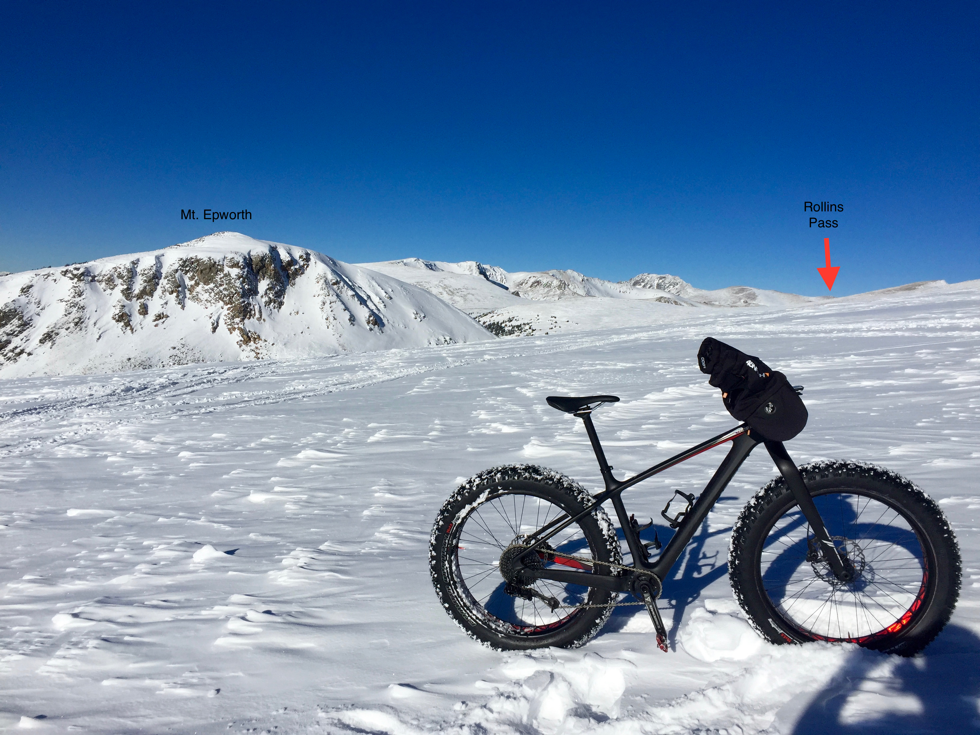
A friendly snowmobiler took my picture while next to the trestle. Mt. Epworth and my destination is just behind me.
Welcome to the tundra. I MADE IT! This is as high as I’ve been in in the winter on any of my rides up here. Rollins Pass is about 2-3 miles in the distance, but the road isn’t groomed in the winter (enough for me to make it on a bike, anyway).
I’m still alive! Despite being very, very cold, there was no wind today – absolutely none. It was awesome up top.
Gratuitous pano…
Looking down towards the Fraser valley from the top. You can see Fraser and Tabernash (my place!) far below.
And there’s the Continental Divide! Just a hundred yards or so away. On the otherside is Nederland and then Boulder.
Looking towards Winter Park we can see the ski resort and the Riflesight Notch railroad trestle where I just came from.
Looking back towards the North we can see Mt. Epworth and Rollins Pass in the distance. If you look closely, you can see snowmobile tracks the more advanced riders have made over to that area.
Further down the hill. In the summer, this rock is just above the main road. The snowmobiles all wind up here for the scenic view.
11,500 ft!
About to descend… this hill, down towards Corona Bowl, was actually too steep to ride up, so I hiked up. Coming down, a minute or so after this shot was taking, I built up too much speed and had a spectacularly fluffy powder crash. A little less air pressure in the tires would have helped that…
Back down at the Riflesight Notch railroad trestle… still early in the season so it is visible.
If you saw my post about hacking the CAN-Interior bus of a JK, you noticed my comments about building an intelligent accessory switching system. I’m pretty far along with that, and would love to get some feedback from the community on features they’d like to see.
Right now my plan is to build something, release it all with open-source and open-hardware so people can build their own, but there’s been enough interest for people who would like to have one built for themselves that I made the following survey. If you have a moment, I would really appreciate your feedback.
Once the survey is all done, I’ll post the results here too so everyone can see the data.
And if you aren’t sure exactly what I’m talking about – it’s effectively a standard relay box in your engine bay, but instead of just toggle switches, it’s smart and listens to your car’s computers and can activate switches when lights go on/off, high-beams, blinkers, ignition – whatever we can think of.
I finished the 1st proof-of-concept for using the CAN-Bus data to control auxiliary relays. It worked great. Attached is a block diagram of what I used, and a longish video of how the testing went.
Jeep Bot Block Diagram
If you want to skip all the bench testing, the actual in-car testing happens at the 11:15 mark of the video.
A few hours after I finished, a bluetooth-low-energy board I ordered showed up. The next step will be to throw that on there so that I can use the smartphone to configure each switch and optionally control them by hand.
Each switch will have the following different possible control states:
always on
manual only
on when interior lights are on
on when high-beams are on
Right after that, I’ll start working on a prototype PCB and housing so I can start testing real versions of this system.
I’ll post the design, schematics and code in progress on my blog so anyone can offer feedback as it gets built.
The Jeep’s Electronic Vehicle Information Center (EVIC) Displays a Custom Message
I have a 2012 Jeep Wrangler Unlimited and have a few projects where I wanted to integrate closely with the vehicle’s electronics. Instead of tapping into the final wiring of the car, I wanted to leverage the vehicle’s own computers to tell my accessories what to do. The end goal being a much tighter and seamless integration, and much less modification to the wiring of the vehicle.
Modern automobiles use a technology called a Controller Area Network, or CAN-Bus, to communicate between the different computers within the vehicle. The use of this technology greatly simplifies the wiring requirements within the vehicle as a large number of components can share a single twisted-pair wiring harness.
There are actually three separate CAN bus systems used in the vehicle: the CAN-Interior (also known as CAN Interior High Speed/IHS), the CAN-C and the Diagnostic CAN-C. The CAN-Interior bus is used for communication between the interior modules of the vehicle, such as the dashboard and radio and runs at 125 Kbps. The CAN-C bus is used by the power train components and runs at 500 Kbps. Finally, there is the Diagnostic CAN-C which also runs at 500 Kbps.
The Diagnostic CAN-C bus is used to talk to a gateway computer, the Totally Integrated Power Module or TIPM. This gateway implements all of the logic needed for onboard diagnostics, and communicates to the other two buses as needed. One effect of this implementation is that data from the other buses is not easily obtained via the data link connector (a.k.a the ODB-II port) underneath the dash. While a tremendous amount of information is available via the diagnostic bus, it isn’t easy to hack or obtain without getting official documentation from the manufacturer directly.
I came across canbushack.com when I was thinking about looking at the CAN-interior bus and was happy to see much of the information I was after is on that bus. Unfortunately, I also found that the implementation has changed quite a bit from the time most of the work was done on that site versus what is in my Jeep today.
Custom Wiring Harness using the Radio C2 Connector
The easiest way to access the CAN-interior bus is the radio C2 harness. I built a pigtail wiring harness by buying a couple of aftermarket radio wiring harnesses, linking them together, and splicing in a pair of wires for the CAN-H and CAN-L connectors. By making a custom pigtail like this I avoided having to alter any of the OEM wiring making for both easy removal and a lower risk of screwing up something.
I originally used an Arduino Uno micro-controller board and a CAN interface shield from SparkFun and SK Pang Electronics. This platform is a prototype for what I will eventually use as the final production solution for my projects, but I quickly found that analyzing and hacking the vehicle’s CAN-Interior bus was too tedious with that solution, for two primary reasons: a) I had to write code to test any hypothesis, and b) I had to be physically connected to the Arduino with my laptop, in the car, in the cold of winter.
Raspberry Pi with CAN Interface Board
To solve both issues, I configured a Raspberry Pi system with a CAN interface board made specifically for it by SK Pang Electronics and a USB WiFi dongle so I could leave the system in the vehicle and login to it from the comfort of my living room. Since the RPi is a temporary research solution only, I only placed into the glovebox, connected the CAN-H and CAN-L wires, and used a USB power supply directly from the vehicle’s 12v auxiliary power port.
Configuring the Raspberry Pi to communicate with the CAN Bus is unfortunately non-trivial, and I will cover that in another post.
What’s great about using Linux for CAN-bus hacking is the plethora of great tools available. The can-utils package in particular contains the command-line tools I used to analyze CAN bus messages and generate my own.
The very first thing to do is to look at the traffic on the bus using the candump utility. This utility does exactly what it sounds like – dumps all of the traffic it sees on the bus to your terminal or to a file. When I first tried candump on the CAN-Interior bus of the Jeep, I started to see data like this:
id:0x402 len:8 rtr:0 data:0xfe 0x02 0x3f 0xff 0xff 0xff 0xff 0xff

id:0x3e6 len:3 rtr:0 data:0x0b 0x11 0x1e

id:0x1e7 len:8 rtr:0 data:0x70 0x00 0x00 0x00 0x00 0x00 0x00 0x00

id:0x208 len:7 rtr:0 data:0x00 0x00 0x6d 0x5a 0x1e 0x01 0x2c

id:0x2d2 len:3 rtr:0 data:0x00 0x33 0x00

id:0x2dd len:4 rtr:0 data:0x05 0x00 0x00 0x00

id:0x2df len:8 rtr:0 data:0x10 0x04 0x03 0xe8 0x0f 0xa0 0x09 0xbf

id:0x286 len:6 rtr:0 data:0x03 0x38 0x00 0x00 0x00 0x00

id:0x348 len:8 rtr:0 data:0x00 0x00 0x00 0x00 0x00 0x00 0x00 0x00

id:0x2d2 len:3 rtr:0 data:0x00 0x33 0x00

id:0x2eb len:4 rtr:0 data:0x1e 0x00 0x64 0xee

id:0x2ce len:8 rtr:0 data:0xff 0xff 0x00 0x00 0x00 0x00 0x00 0x00

id:0x2b0 len:4 rtr:0 data:0x02 0x00 0x00 0x00

id:0x211 len:8 rtr:0 data:0xff 0xff 0xff 0xff 0xff 0xff 0xff 0xff

id:0x19f len:8 rtr:0 data:0x01 0xff 0x00 0xff 0xff 0xff 0xff 0x00

id:0x370 len:8 rtr:0 data:0x00 0x00 0x00 0x00 0x00 0x00 0x00 0x00

id:0x214 len:7 rtr:0 data:0x04 0x0d 0xba 0x00 0x14 0xb4 0x00

id:0x286 len:6 rtr:0 data:0x03 0x38 0xc0 0x00 0x00 0x00

id:0x2eb len:4 rtr:0 data:0x1e 0x00 0x64 0xef

id:0x2ce len:8 rtr:0 data:0xff 0xff 0x00 0x00 0x00 0x00 0x00 0x00

id:0x211 len:8 rtr:0 data:0xff 0xff 0xff 0xff 0xff 0xff 0xff 0xff
What a mess! That amount of data flashed across the screen in less than a quarter second and began to repeat in long cycles. It was very difficult to look at such a stream of data and detect when changes occurred based upon user action. Luckily, the can-utils package includes another awesome tool called cansniffer that can help with that very problem.
When you run cansniffer, it looks at the traffic for specific message ids and begins to filter out repeating messages that do not change. After a few seconds of startup time, the Jeep is left with the following changing data while in accessory mode:
It was clear from watching cansniffer what some of this data was.
Message Id $219 is the vehicle identification number repeated over and over. The first byte of the message is the message #, $00 through $04 with the VIN split across each.
Message Id $3e6 is a clock of the hours, minutes and seconds since the vehicle was turned on.
I was then able to operate switches in the vehicle and discover the following messages in short order:
244 81 00 39 C3 80 # Driver's door open, byte 0

244 80 00 39 C3 80 # Driver's door closed, byte 0

208 01 22 6d 5a 1e 01 2c # Left blinker on, byte 0

208 00 22 6d 6a 1e 01 2c # Left blinker off, byte 0

208 02 22 6d 5a 1e 01 2c # Right blinker on, byte 0

208 00 22 6d 6a 1e 01 2c # Right blinker off, byte 0

1e1 00 00 10 65 00 00 00 00 # Steering wheel position, bytes 3 & 4

2e0 00 01 47 21 ff ff 0c # Brake pedal depressed, byte 4

2e0 00 01 47 20 ff ff 0c # Brake pedal released, byte 4

2e7 84 1c 00 00 00 00 87 # Parking brake on, byte 0

2e7 04 1c 00 00 00 00 87 # Parking brake off, byte 0

292 00 49 33 00 00 48 28 # Throttle pressed, byte 3

2a8 00 01 00 00 00 00 # Windshield wipers, byte 3

2e5 03 # Rear wiper

2d2 01 06 00 # 4WD-HI

2d2 04 04 00 # 4WD-LO

2d2 00 03 00 # 2WD
Some of the data in each message is immediately apparent and others will take some more analysis to figure out what each byte represents. I was particularly surprised to see that the steering wheel movement t generated any data at all on the CAN-Interior bus.
Some actions result in multiple messages being generated. In particular, the lights appear to generate two message id’s when state is changed, one to two with id $208 and another with id $2e1. Here’s what I’ve found so far:
208 00 22 6d 5a 1e 01 2c # Lights on w/ fogs

208 58 22 6d 51 1e 01 2c

2e1 1a
208 00 22 6d 5a 1e 01 2c # Lights off w/ fogs
2e1 1b
2e1 1b # Fogs on
2e1 0b # Fogs off
2e1 0a # Lights on w/o fogs
2e1 0b # Lights off w/o fogs
The Radio generates a lot of data, too:
29e 00 03 97 20 02 ff ff ff # Change to FM 91.9
291 09 01 05 30 f0 00 07 # Change to satellite, w/ no signal
293 00 00 b8 20 02 ff ff ff
Message id $295 is the most fun, as any message broadcast with that id will appear on the vehicle’s EVIC message line, assuming you have disabled the ECO option from being displayed.
Stay tuned for more information about the bus, how to setup both the Arduino and Raspberry Pi to talk to a CAN bus, and details about upcoming projects.